Showing posts with label opengl. Show all posts

Friday, 4 March 2011

The BOIDS are back in town!


During the last lesson of complex systems course, prof. Vizzari showed a crowd simulation based on BOIDS, an intriguing model invented by Craig Reynolds in 1986 that simulates bird flocks, fish schools and all that kind of self-organizing masses of living stuff. The basic model is based on three simple assumptions:
  1. each boid moves toward the other flockmates (cohesion)
  2. each boid moves away from crowded situations (separation)
  3. each boid follows the direction of the rest of the flock (alignment)
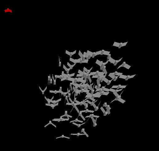
Even in its simplest formulation the model works very well, and gives a pleasant feeling of viability. I turned the model from 3D to 2D, by putting all boids on the y=0 plane, and here we go: we have a simple crowd simulator.

There exist several approaches to crowd simulation (like cellular automata or multi-agent systems) but I do think that BOIDS have many interesting capabilities.

In fact, one of the open issues in crowd simulations is the sponteneous formation of groups because of common goals, shared costumes, socio-political aspects, familiar relationships and so on. BOIDS leave a lot of space for embedding this wide spectrum of behaviours, whilst the model itself mantains the proxemic distances between people and let them gather peacefully, by the rules decribed above.

The video I embed shows my model in a simple scenario made of four groups (yellow, red, green and blue). Green people have their own goal to follow; red and blue have a shared one. Yellow people just walk around the space, with no specific purpose. In the middle of the screen there's a strong repulsor which keeps boids away. The dynamic works as I expect: there's the formation of clusters, boids belonging to the same group tend to aggregate and find their way even in overcrowded situations. What's fascinating is the emerging, unexpected behaviour of yellow ones: some of them hold still, some dodge the crowd, many other enter the moving groups and follow them wherever they go, conditioned by the first rule.Very nice.
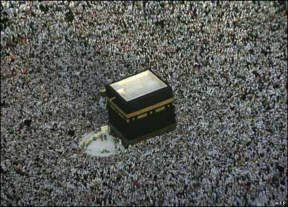
Hajj - the annual pilgrimage to Mecca - is
one the most interesting scenario to simulate
Still, there's a lot of work to do that I'll share with my brilliant coursemate Michele. For instance, we'll try to identify the correct parameters that fit the experimental results, incorporating Elias Canetti's proxemic dynamics as well. We also could find a way to introduce different kind of non-penetrable contraints (walls, doors, and such). There's the problem of instructing complex goals (like finding a way to an exit in non-straight situations or following a leader), with an eye to stability and realism. Finally, there's lot of optimization to do: I wrote the code as general classes and new rules can be easily introduced by pushing a new function pointer to a "rules" vector. That's very flessible, allows a very rapid prototyping but it's very inefficient: the naive algorithm is O(n²), because every boid's position needs to be compared with the rest of the flock, and every rule is computed on its own, adding a costant factor. Too slow for serious business like sport events, concerts, and religious pilgrimages, just to name a few of the typical simulations that require millions of individuals at once.

Friday, 9 October 2009

The evolution of parallax

Once upon a time, videogames were bidimensional, and it was fine.
One day, in order to give some depthness to the scene, programmers introduced a technique called parallax scrolling: by moving the elements of the background at different speed, a sense of spatiality and immersivity emerged.

The sensation was outstanding for the age, but the drawback was a very high computational cost, that kept this strategy confined on 16bit machines. With the arrival of 3D graphics, parallax scrolling was abandoned.

In 2001, a Japanese researcher named Tomomichi Kaneko introduced a brilliant modification of texture mapping able to provide "the capability to represent the motion parallax effect to the textures placed on 3D objects". His algorythm was basically a normal mapping, whose strategy is to use a texture's RGB channels to map a 3D normal, overriding the vectors on surfaces; Tomomichi basically suggested to enhance the feeling of movement by displacing textures by a function of the view angle in tangent space.

The tangent space itself is the trick behind all, and let us compute stuff in a comfortable space: instead of doing tons of computations in world space, we "look at things" from the top of the texture.

The generation of the special coordinates (normal, tangent and binormal) is done "client side" during the geometries loading, and sent to the server as vertex attributes.

The normal mapping itself requires at least a couple of textures to be sent and, guess what, I faced again the limits of DirectX9 compliant boards. I wanted to keep at least 4 lights on the scene, and use three textures (diffuse, normal map, and a gloss map). I quickly overflowed the capabilities of my VGA card and learnt an interesting thing.

GLSL is paranoid

I'm not sure it's a GLSL thing, but that's it: it's paranoid. It expects the worst scenario to happen. And therefore does not optimize a thing. I explain.

Suppose you have a code similar to this:

void DoSomething(int number_of_light) {
  ...
  Use( gl_LightSource[number_of_light] );
  ...
}

void main() {
  ...
  for (int i=0; i<TOTAL; i++) dosomething(i); 
  ...
}
What do you expect? You may think that your GLSL compiler will smartly recognize the boundaries of your  request and will fetch from memory just the informations about the TOTAL lights you're going to use. Well, wrong: it will allocate all MAX_GL_LIGHTS informations as uniforms. A mess. By keeping your code so general you instantly reach the limits of the card and the program does not link anymore. I didn't know about this (never read about that) and there's no way to optimize it. You must do several fetches to each specific light source you want to use on the scene, and that way you keep the uniforms count down. Weird.

Tuesday, 6 October 2009

Sprites, animations, and 3D textures


During the 80s real 3D was just a chimera. Apart some pioneer, embryonic vectorial engine, computer graphics was achieved by using small bitmap images, stored in contiguous memory locations: the sprites.

Borrowing from traditional techniques, sprites were animated by drawing the animations in separate images (a classic example) and displaying them in sequence, creating the feeling of dynamism.

Before the transition from 16 to 32 bits systems, many hardware engineers introduced several solutions for smoothly rendering lots of sprites on screen (eg.: DMA, dedicate co-processors, and so on), but they were soon forgotten as full 3D engines appeared and stole the scene.

So, why should anyone bother getting the sprites back from the past? Well, they could be useful even today, because there are aspects of computer graphics which work better pre-rendered: explosions, flames, debris, smoke and all that stuff it's too expensive to compute real-time.

An higher dimension
As I wrote, sprites animations used to be stored in different memory locations, and the pointer to the current frame was given to the scanline renderer. We could do the same now, creating several bitmaps and rendering them on screen. But this idea has a couple of drawbacks: we need to create many different texture objects for the same "thing" and, in order to obtain a smooth transition, we must load plenty of slightly different images.

Another idea could be to load a huge texture featuring all frames on it, and display the current one playing with offsets: this fixes the first issue, but not the second one.

A nice way to achieve both is to use a 3D texture. A 3D texture is, basically, a stack of normal 2D textures. The number of "stacks" is called "depth", and it's a parameter we must give during initialization. Pay attention here: as normal textures, even depth must be a power of 2.

Why do 3D texture give us no drawbacks? First, they aggregate lot of textures in one single texture object. Second, when you make request for an intermediate stack, you can be given the interpolated texture. This is transparent by turning on linear filtering, and does not impact on performances.

A nice explanation of this technique can be found here. The following step is billboarding, that is keeping the sprites frontal to the viewer. There's a cool NeHe tutorial about it. If you want to play with sprites but don't have time/skill for producing your own explosions, check this out.

Thursday, 1 October 2009

Does your shader seamlessly compile, but inexplicably doesn't link?

Maybe it's due to the GL_MAX_VARYING_FLOATS limit.

If you go crazy obtaining the error "Fragment shader(s) failed to link", try reducing your explicit -and implicit- varyings variables.

It turns out that, for instance, you cannot combine 8 textures and 8 "blinn-phong light sources" inconsiderately, because if you would like to interpolate textures and light vectors, you end up using (8+8)*4 = 64 varyings floating point variables!

Keeping out useless textures coordinates (z,w) and the alpha channel, by using custom varyings instead of the built-in ones, you can go down to 8*2+8*3 = 40, which is lower than 44, limit for most common DX9 compliant boards.

Tuesday, 29 September 2009

Fixed functionality beats programmable pipeline 10:0?


Something's terribly wrong somewhere... Blinn-phong shader is wasting all GPU's power!

I've done some optimization, but I'm afraid that writing general code, good for all seasons is not the best way to achieve performance.

I can't imagine how many compromises serious 3D engines hide under the hood!

Monday, 14 September 2009

Meshes from points

It's been an hard job, but an interesting experience. My 3D engine "PLT" now features its own Delaunay triangulation. Now I can turn an arbitrary set of points into a continue, smooth, tridimensional mesh.

The algorythm is well explained on Wikipedia, and practically consists in breaking an encompassing triangle in smaller ones, ensuring that every triangle does not "contain" any other vertex.

This check is the heart of the algorythm and it's achieved by verifying that every vertex lie outside the circle identified by the three points of each triangle.

There's a lot of geometry, trigonometry and even a little bit of calculus inside of this piece of software; the exams of discrete algebra and calculus found a practical, consistent application.

The next step is to speed it up: the algorythm is far from its potential O(n log n) possibilities and must be optimized. It seems to be even greater than the expected O(n²), probably due to the STL internal sorting algorythms.

Thanks to Erazor for the idea and Gerry for the math support. =)

Saturday, 29 August 2009

The farm of convexity

I'm working on my first scientific visualization "job" in these days; it's a computational fluid dynamics simulation, which has to be displayed to make some inference.

Instead of importing datas into VTK, I loaded them into my 3D framework. And it was a fail, because of three conceptual errors:
  • my engine was written to display polygons; instead, we have ~3000 point samples which have to be manipulated in different ways
  • datas were in double precision! all my framework used to be in floating point, and the loss of data was unacceptable
  • a single point dispersed in a sea is not recognizable; its impossible to make inferences. Therefore, I thought it could be nice to partition data in sets, and display a convex hull of similar points.

Convex envelopes
Given a set of points, a convex hull is the minimum convex boundary which contains them.

There exist many algorythms for computing it, by my choice fall on Jarvins' March: also called "the gift wrapping algorythm", consists in... well... rotating around your set trying to keep your sheeps inside the corral!
  1. the algorythm starts choosing a single point which surely lies on the hull (p0 in the image)
  2. you trace a vector from your point to any other point in your set
  3. [important] you compute the angle formed by an axis and the previously traced vectors, and you pick the minimum one by using the arcotangent.
  4. now you have the second point and iterate from 2; on step 3 you'll naturally won't pick just the minimum, but you'll check that the new angle is greater than the last one
If "h" is the number of points in the convex hull, and "n" the number of points in the set, the complexity of this algorythm is O(nh), which is cool.


Going back to the CFD job, I used the convex hull to display the set of points featuring the highest values. Well, the first screenshot shows how useless it is: the points are too far, and this representation, again, does not help us in any way. Probably, a better way could be to keep together the closest points, using some kind of "distance" function. I'll work on it.

Wednesday, 22 July 2009

Wavefront .OBJ files & Vertex Buffer Objects


OBJ files are handy for many reasons:
  • they're text files
  • well documented
  • easy to parse
  • and many professional softwares can export them

This is why they are so popular as standard files for 3D graphics.

Their structure is basically a (long) list of vectors definitions (spatial, normals, texture coordinates, and so on) followed by a (long) list of structures defining faces. What are faces? Faces are tuples of indexes, which point specific vertexes, normals and texture coordinate in the previous lists. At least three vertexes are needed for each face, because it forms a triangle, that is the smaller polygon we can create.

Why is this needed? Well, because a single vertex could be shared by many faces (=polygons). That's important in real-time 3D programming, because avoiding redundancy is good for performances!

This is the very same idea behind OpenGL's indexed vertex arrays: rather than sending to the video card a list of vertexes, normals and texture coordinates (the so called immediate mode) we prepare a couple of arrays filled with informations, and another array of indexes which tell OpenGL what vertex use in a certain primitive.

Sounds good, uh? Well, there is a couple of drawbacks actually.

The biggest is that every index points simultaneously at vertex, normals and texture arrays! For instance, if our first index is "1", that face points vertex[1], normal[1] and texture_coord[1]. That's a real nightmare, because there's no ensurance that our modeling softwares will produce .OBJ files featuring correctly ordered lists! Moreover, there's often a few of vertexes (which are often shared by many faces) and lot of normals!

So what?? Well, OpenGL does not aid us in any way: you gotta solve with your hands. My solution is the following:
  • parse the OBJ file, loading vertexes, normals, and faces;
  • from faces, create a definitive vertex index and a temporary arrays for normals and textures coordinates;
  • for each i in number_of_indexes do
    definitive_normal_array[ index_array[i] ] :=
    Temporary_normals_array[ TemporaryNormalIndexes[i] ]
And there you go, you have correct normals bound to the right vertex. You could even have time for re-normalizing them, if they aren't.

The most interesting way for drawing this series of arrays is the use of Vertex Buffer Objects (VBO). They're similar to the indexed vertex arrays, but have interesting features... like dropping geometries in the fastest video card memory and use it! The boost of performances is impressive, and they are easy enough to deal with.

My PLTmesh::Draw() method is this:

// PLT_VBOnames are references to the VBOS - see glGenBuffers()

glEnableClientState(GL_NORMAL_ARRAY);
glBindBuffer(GL_ARRAY_BUFFER, PLT_VBOnames[2]);
glNormalPointer(GL_FLOAT, 0, NULL);

glEnableClientState(GL_VERTEX_ARRAY);
glBindBuffer(GL_ARRAY_BUFFER, PLT_VBOnames[0]);
glVertexPointer(3, GL_FLOAT, 0, (char *) NULL );

glBindBuffer(GL_ELEMENT_ARRAY_BUFFER, PLT_VBOnames[1]);

glDrawElements(GL_TRIANGLES, this->IndexesArray.size(), GL_UNSIGNED_INT, (GLvoid*)((char*)NULL));

glDisableClientState(GL_VERTEX_ARRAY);
glDisableClientState(GL_NORMAL_ARRAY);

glBindBuffer(GL_ARRAY_BUFFER, 0);
glBindBuffer(GL_ELEMENT_ARRAY_BUFFER, 0);
Quite simple and clear! :)

Monday, 20 July 2009

We meet again, dear wheel

Soon after my experience at CINECA, I took the decision to implement my own 3D engine.

I'm not trying to develop the ultimate graphic experience, of course. I just wanna own a set of libraries useful for easily handling and displaying scientific information, without too much effort.

Actually, I tried to avoid the huge effort of programming a whole 3D framework from scratch by using OpenSceneGraph; well, I tried, but it turned out that making it work was going to take more time than coding my own! Furthermore, I probably won't make always use of a scenegraph for my representations, so here we go.

The first thing I focused on are shaders: PLT is going to be a GLSL-centric engine. The fixed pipeline is still supported, more or less, but there's no future for it, and it's time to leave it alone.

Besides the qualitative leap that shaders allow (the screenshot shows a comparison between fixed functionality and a phong-blinn lighting), there's another huge benefit: the engine can easily be ported onto embedded systems. That's the second aspect I'm focusing on: portability. I want PLT to run on every system I could code on: Windows, Linux, and Windows Mobile.

What misses at the moment? A true geometry loader, for instance. There's already full support for vertex buffer objects, and I can manually load vertexes, normals and so on, but I must code at least an handy .OBJ loader.

As I told, there's no a scene graph, not even a rudimentary one. I'll surely need a bunch of matrix functions for manipulating my objects loaded server-side.

And naturally, I'm going to extend the PLTlights classes for shadow maps support as soon as possible! :)

Sunday, 2 November 2008

Expensive state changes

Everytime you want a primitive to be multi-sampled - in order to convert its alpha values into coverage patterns - you are supposed to explicitly ask for it by enabling GL_SAMPLE_ALPHA_TO_COVERAGE.

I thought that keeping this feature enabled for non-translucent primitives was a waste. I was wrong! It's continuosly changing this state that cuts down performances!

Therefore, you're going to prefer to let alpha2coverage enabled whereas supported, and enjoy the terrific boost of performances.

Tuesday, 28 October 2008

Don't you know, talking 'bout the convolution it sounds like a whisper

Hard shadows destroy realism. It's a matter of fact, they look too unnatural, expecially if the rest of the scene appear softly shaded and we overlap a simulated cone of light.

Plenty of solutions have been proposed. Furthermore, Nvidia cards are so smart that they automatically apply the percentage closer filtering on shadow maps. ATI cards don't, but proposed a pretty way to implement it (by using their proprietary multiple fetching primitives).

I don't want to use proprietary features, which could lead to unexpected situations, so I took the decision to try something new: by using stencil buffers, I'm gonna separate "potentially shadowed" texels and blur them, with some kind of convolution filter:


Pros: it's REALLY fast (dirt work is done via fragment shader), it's lightweight (just an additional RGB texture is required), and it's image-space based, so I don't need to program lighting equations for each texture unit in the shader!

Cons: additional rendering steps are needed, one for each light; self-shadowing artifacts are supposed to emerge and there's no difference between shadows near and far away from light (which is best aspect of smarter algorythms like PCSS or VSM).

We'll see. In the meanwhile, I express my disappointment for ATI's engineers who didn't really implement glConvolution*D() in their drivers :| .

Saturday, 18 October 2008

Causticity

A preliminary shot of my "translucency shadow mapping" engine, showing just the "filtrating light" layer. Light illuminates the glass, which projects its texture on the transparent radiation box, which is supposed to project on the wall as well.

Seems working, but actually it doesn't.

The reason is subtle: the more translucent a surface is, the more it shouldn't stop the light; this means that the projected shadow should appear brighter and colorful, but it does not.

This is due to the fact that I create a sort of translucency map by rendering the translucent objects from light's pov, and the resulting image gets darker as the alpha decreases! Some kind of "alpha inversion" is needed, maybe pre-calculated. But this means much more memory, linearly dependent from the number of lights and the resolution of viewport!! Not suitable.

A better solution should be caustic mapping, which is definitively one of the coolest algorythms I've ever seen. The results are impressive, but there are (as usual) some drawbacks: additional geometries (for refractive vertex grid and the projected points), no way to sum up many translucent contributions and so on. It would be interesting to implement it some day, but there's no time to play with it right now.

Wednesday, 15 October 2008

Order indipendency

Translucency and transparency are not trivial in realtime CG.

Peaceful ray tracers take their time to throw lines inside and outside objects, while rasterizers have no peace quickly collecting incoming fragments. In order to alpha blend them, they must arrive in a precise order: the farthest, the earliest.

This limitation has a deep impact when rendering a scene: you have to sort your objects in order to obtain a correct blending. Moreover, there are pathological cases which cannot be solved by using standard techniques (such as object1 covered by object2 covered by object3, which is covered by object1 again).

I googled a bit and found out that several different solutions has been offered to obtain the "order indipendent transparency", but just two are really cool and do not make use of external shaders: depth peeling and multisampled alpha coverage. The first one is brilliant: subdivide the scene by peeling away closest depths, and blending everything at the end. Naturally, many renders are required and performances fall.

The second one is less sophisticated, but interesting. It uses the additional samples taken by multisampling (for anti-aliasing and similar) and use the alpha information to create a coverage mask of these samples.


The final composition is stunning, but a correct irradiance on the shadowed object is still missing.

Tuesday, 14 October 2008

Projective light cone

Due to its intrinsic nature of texture, the shadow map looks squared.

A nice way to improve its appearance is to use the very same coordinates that project the shadow to map an additional bitmap, which simulates the bottom of the light cone produced by the "spotlight".

Now it would be cool to simulate the whole light cone by using some kind of volumetric escamotage.

Wednesday, 1 October 2008

Aliasing galore and FBOs

When you're going to write a 3D shadows engine, your choice is basically restricted to two possibilities: shadow volumes or shadow mapping in one of its flavours.

There's no reason to choose shadow mapping but the performances: shadow volumes are more accurate, because a shadow map is a simple texture spread on a scene and used for depth comparisons. It's obvious that texture's detail affects render realism, and all sort of aliasing will happen.

The quickest way to improve an image-space based algorythm is to improve the image.. space! You should render the scene with higher resolution. But you can't. Reason is that even if you raise the viewport size, anything greater than the actual container window will be dropped.

There are also restrictions for the texture shape and dimensions, but you could get around them using some of the latest extensions (ARB_texture_rectangle, ARB_texture_non_power_of_two)... but anyway, the problem remains: we are in need for detail. There are sophisticated geometric solutions, such as trapezoidal/perspective shadow maps and cascading shadow maps, but we could simply... render elsewhere!

Here come frame buffer objects. They are basically "containers" that you can use as targets for your renders. You can also use them to directly render on a texture, and this is our case: we render there our huge shadow map.


The difference is clear and performance hit is not dramatic. The coolest part is that using FBOs does not take modifications to previous routines (just bind the directly generated texture as usual!), and can be turned on in every moment. Approved!

Friday, 26 September 2008

Pseudo gamma correction

As several lights add up in the scene, several accumulations happen in the background, flattening average contrast and luminance. In order to have the colorful scene back, we can tweak the accumulation buffer a bit using the GL_MULT function of glAccum API, and passing as multiplication factor the result of 1+γ*numberOfLightSources.

Here's a screenshot:


compared to the previous images, also with γ=.2 the improvement is pretty evident.

Wednesday, 24 September 2008

Put on the red light

Who said lights are just white? Introducing an almost coherent red light.

More then ever, hard shadows and light's cone edge appear too unnatural. Some kind of linear filtering is required here, maybe a PCF for shadows and a bit of blur for cone's boundaries.

Tuesday, 23 September 2008

N lights are better than one

Here we go! Accumulation buffers allowed an easy drawing of multiple light sources and relative shadows.

The trickiest aspect was the balance of exposition: every light features its accumulation factor and the light contributions are supposed to be under 1, in order to avoid overexposition.

It could be a cool effect, anyway. =)

Sunday, 21 September 2008

Accumulation buffers

Shadow mapping is working correctly, but only one (spot!) light at a time.

Nature is very different, so engine has to be changed a bit. How can one sum the contributions of several different lights, placed around the scene? Accumulation buffers can do the trick! These supplementary buffers will sum the RGB values of our different takes from any single light and return the final composite bitmap.

This screenshot shows a typical application of accumulation buffers: motion blur. With a very minimal modification of original dev-cpp's GLUT example we can achieve this interesting effect.

In pseudocode:

for (;;) {
glClear (GL_COLOR_BUFFER_BIT | GL_ACCUM_BUFFER_BIT)
const range = 10
for i=1 to range do {
render(i);
glAccum(GL_ACCUM, 1.0f/range)
}
glAccum(GL_RETURN, 1)
swapBuffers
}


Three brief comments.

First, the range means "how many different takes we wanna use for motion blur overlaps". This example is not optimized in any way and renders 10 times the scene for each pass.

Second, the render is bound to the i variable. The meaning is that we want to simulate movement, so it makes no sense to render 10 times the same static scene. In the example, I did the objects rotate "i degrees".

Third, the accumulation command takes a floating point value, which tells how much of the RGBA values we want to sum up in the buffer. Given that these values are clamped in the [0,1] range, and we're going to sum 10 shots, we can set these values in a way that the final count is 1: 10*(1/10) = 1.

The same philosophy shall work for multiple lights: we sum up the n contributions of n lights.

Friday, 19 September 2008

Young 3D engines suffer acne

As the engine grows up, I refactor some routine. Cleaner code allows me to use some higher level function, like a 3Ds objects loader. And here appears a well-know issue: z-fighting.

Even on a surface closest to the light source, you will always discover minor differences in the values associated with the R texture coordinate(...). This can result in "surface acne"(...). You can mitigate this problem by applying a depth offset when rendering in the shadow map:

...
glEnable (GL_POLYGON_OFFSET_FILL);
glPolygonOffset (factor, 0.0f);
...

(...)A balance need to be struck when it comes to polygon offset usage.

from OpenGL superbible 4th edition by Richard Wright (Wesley).
That balance is not so easy to achieve; as Nvidia says in its papers, it's really matter of art.